ESP8266 IoT Control System with OLED Display and UDP Protocol
Welcome to another exciting IoT project where we combine the power of ESP8266, an OLED display, and UDP communication to create a versatile remote control system. In this blog post, we’ll delve into the details of the Arduino code and hardware setup that enables remote control of a vehicle’s direction.
Components Used
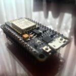
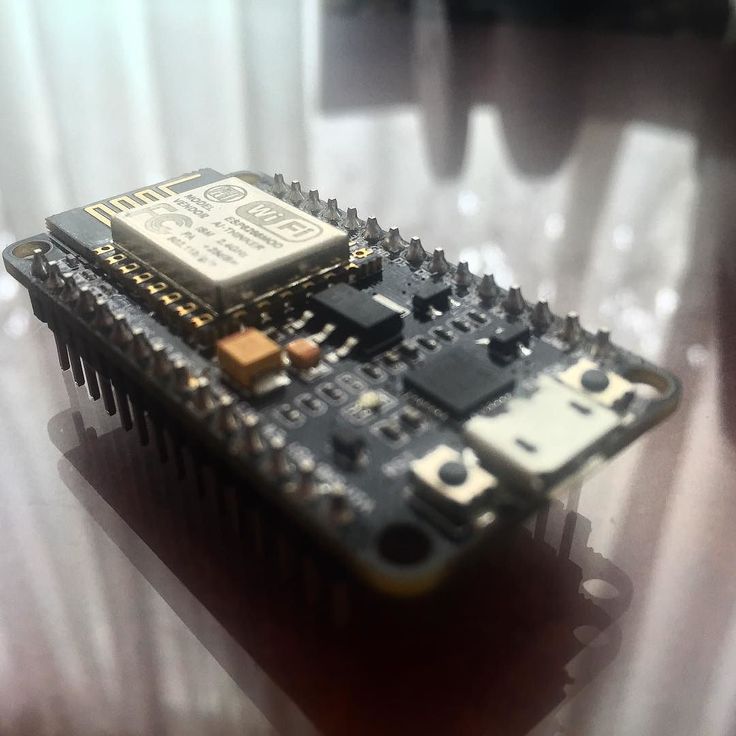
- ESP8266-based NodeMCU
- OLED Display (128×64 pixels)
- WiFi Module for Internet Connectivity
- UDP (User Datagram Protocol) for Data Transmission
Project Overview
Setting Up the Hardware
- Connect the OLED Display: Utilize the SPI and I2C communication protocols to connect the OLED display to the NodeMCU. This establishes a communication link, allowing the NodeMCU to send data for real-time updates on the display.
Software Development
The heart of the project lies in the Arduino code running on the NodeMCU. Below, we’ll explore the key functionalities of the code:
1. WiFi Connection
The NodeMCU connects to a specified Wi-Fi network using the provided SSID and password.
WiFi.begin(ssid, pwd);
while (WiFi.status() != WL_CONNECTED) {
    // Wait for the connection to be established
    delay(1000);
}
2. UDP Communication
The program utilizes UDP for data transmission. The NodeMCU listens for UDP packets on a specific port and reacts to commands such as “up,” “down,” “left,” and “space.”
WiFiUDP UDP;
UDP.begin(UDP_PORT);
int packetSize = UDP.parsePacket();
if (packetSize) {
    // Read the packet into the receivedData char array
    UDP.read(receivedData, sizeof(receivedData));
    // Process the received data and respond accordingly
}
3. OLED Display
The OLED display is used to provide real-time feedback on the device’s status. Various functions display information about the WiFi connection, UDP port, signal strength, and vehicle direction.
// Example: Displaying WiFi connection information
displayHomeScreen();
display.print("Rx Key: ");
display.println(receivedData);
display.display();
4. Vehicle Direction Control
The vehicle’s direction is controlled based on the received UDP commands. The program increments or decrements the FORWARD and SIDE variables accordingly.
if (strcmp(receivedData, "up") == 0) { FORWARD = min(FORWARD + 1, 99); }
if (strcmp(receivedData, "down") == 0) { FORWARD = max(FORWARD - 1, -99); }
if (strcmp(receivedData, "right") == 0) { SIDE = min(SIDE + 1, 99); }
if (strcmp(receivedData, "left") == 0) { SIDE = max(SIDE - 1, -99); }
5. Gradual Incremental Reset
When the “space” command is received, both the FORWARD and SIDE variables are gradually decremented towards 0, providing a controlled stop.
if (strcmp(receivedData, "space") == 0) {
    // Increment both FORWARD and SIDE towards 0
    while (FORWARD != 0 || SIDE != 0) {
        // Gradually decrease FORWARD and SIDE values
        FORWARD = (FORWARD > 0) ? max(FORWARD - 1, 0) : min(FORWARD + 1, 0);
        SIDE = (SIDE > 0) ? max(SIDE - 1, 0) : min(SIDE + 1, 0);
        delay(10);
    }
    displayHomeScreen();
}
Conclusion
This IoT control system showcases the integration of ESP8266, OLED display, and UDP communication for remote vehicle control. The combination of hardware and software provides a versatile platform for further IoT projects and applications. Feel free to modify and expand upon this project to suit your specific requirements.
Happy tinkering!
Full Download :
#include <SPI.h> //Lib for SPI for PC to Arduino board
#include <Wire.h> //Lib for I2C communication between NodeMCU to OLED
#include <Adafruit_GFX.h> //lib for OLED
#include <Adafruit_SSD1306.h> // lib for OLED
#include <ESP8266WiFi.h> // lib for wifi
#include <WiFiUdp.h> //Library for UDP data transmission

#define SCREEN_WIDTH 128 // OLED display width, in pixels
#define SCREEN_HEIGHT 64 // OLED display height, in pixels

#define ssid "Home"  //SSID name
#define pwd "xxx"  // SSID Password
#define UDP_PORT 4210  // UDP data port

// Declaring the Variables
WiFiUDP UDP;
char receivedData[255];
char packet[255];
int32_t rssi;
char reply[] = "packet Received.";
int FORWARD = 0;  // Variable for  Vehicle direction PID forward
int SIDE = 0;  // Variable for  Vehicle direction PID Back ward

#define OLED_RESET     -1 // Reset pin # (or -1 if sharing Arduino reset pin)
#define SCREEN_ADDRESS 0x3C ///< See datasheet for Address; 0x3D for 128x64, 0x3C for 128x32
Adafruit_SSD1306 display(SCREEN_WIDTH, SCREEN_HEIGHT, &Wire, OLED_RESET);

//for OLED scrolling effects ---------------------------------------------------------
const int maxLines = 8; // Maximum lines to display
String textBuffer[maxLines];
int currentLine = 0;
void updateDisplay() {  //Display buffer
  display.clearDisplay();
  int y = 0;
  for (int i = 0; i < maxLines; i++) {
    int index = (currentLine + i) % maxLines;
    display.setCursor(0, y);
    display.println(textBuffer[index]);
    y += 8; // Adjust this value based on the text size and font
  }
  display.display();
}
void addLineToBuffer(String line) { //adding new line to the displayu buffer
  textBuffer[currentLine] = line;
  currentLine = (currentLine + 1) % maxLines; // Wrap around if needed
}

// Function to connect to WIFI------------------------------------------
void connectToWiFi() {
  addLineToBuffer("Connecting to Wi-Fi...");
  updateDisplay();
  WiFi.begin(ssid, pwd);

  while (WiFi.status() != WL_CONNECTED) {
    display.clearDisplay();
    display.setCursor(0, 10);
    display.setTextSize(1); // Size of the test
    display.setTextColor(WHITE); // Colour of text
    display.println("Connecting..."); // Display static text
    display.display();
    delay(1000);
  }
  addLineToBuffer("Connected.");
  addLineToBuffer("IP address: ");
  addLineToBuffer(WiFi.localIP().toString().c_str());
  updateDisplay();
}

void displayHomeScreen(){
  display.clearDisplay();
  display.setTextSize(1);
  display.setCursor(0, 0);
  display.println("WiFi Connected.");
  display.println("  ");
  display.print(ssid);
  display.print(" : ");
  display.println(WiFi.localIP().toString().c_str());
  display.print("UDP port: ");
  display.println(String(UDP_PORT));
  display.print("Power : ");
  rssi = WiFi.RSSI();
  display.print(rssi);
  display.println(" dBm");
  display.println(" ");
  display.print("F/B :");
  display.print(FORWARD);
  display.print(" * R/L :");
  display.println(SIDE);
  display.display();
}

void displayF1() {
    display.clearDisplay();
    display.setCursor(0, 0);
    display.setTextSize(1); // Size of the test
    display.setTextColor(WHITE); // Colour of text
    display.println("DISPLAY SCREEN F1"); // Display static text
    display.display();
}

void displayF2() {
    display.clearDisplay();
    display.setCursor(0, 0);
    display.setTextSize(1); // Size of the test
    display.setTextColor(WHITE); // Colour of text
    display.println("DISPLAY SCREEN F2"); // Display static text
    display.display();
}

void displayF3() {
    display.clearDisplay();
    display.setCursor(0, 0);
    display.setTextSize(1); // Size of the test
    display.setTextColor(WHITE); // Colour of text
    display.println("DISPLAY SCREEN F3"); // Display static text
    display.display();
}

void displayF4() {
    display.clearDisplay();
    display.setCursor(0, 0);
    display.setTextSize(1); // Size of the test
    display.setTextColor(WHITE); // Colour of text
    display.println("DISPLAY SCREEN F4"); // Display static text
    display.display();
}

//-----------------------------Full setup ------------------------------------------
void setup() {
  // put your setup code here, to run once:
  Serial.begin(115200);
  //------------------------------OLED setup ----------------------------------------
  if(!display.begin(SSD1306_SWITCHCAPVCC, 0x3C)) { // Address 0x3D for 128x64
    Serial.println(F("SSD1306 allocation failed"));
    for(;;);
  }

  display.clearDisplay(); //To clear the display
  display.setTextSize(1); // Size of the test
  display.setTextColor(WHITE); // Colour of text
  WiFi.mode(WIFI_STA); // Set WiFi to station mode
  WiFi.disconnect(); // Disconnect from an AP if it was previously connected
  WiFi.begin(ssid, pwd); //Connect the Wifi module to the provided access point with the given username and password.
  while (WiFi.status() != WL_CONNECTED){
    display.clearDisplay(); //To clear the display
    display.setCursor(0, 10); // Starting point of the cursor
    display.println("Connecting to Wifi..."); // Display static text
    display.display();
  }
  UDP.begin(UDP_PORT);
  displayHomeScreen();
}

void loop() {
  // put your main code here, to run repeatedly:
  // Check the Wi-Fi connection status periodically
  if (WiFi.status() != WL_CONNECTED) {
    display.clearDisplay();
    display.setTextSize(1);
    addLineToBuffer("Wifi Disconnected..");
    updateDisplay();
    connectToWiFi();
  }

  int packetSize = UDP.parsePacket();
  if (packetSize) {
    // Read the packet into the receivedData char array
    UDP.read(receivedData, sizeof(receivedData));

    // Null-terminate the char array
    receivedData[packetSize] = '\0';

    // Print the received data to the OLED SCREEN
    displayHomeScreen();
    display.print("Rx Key: ");
    display.println(receivedData);
    display.display();

    // Check if received data is "up" Increment FORWARD and ensure it doesn't exceed 255
    if (strcmp(receivedData, "f1") == 0) { displayF1();}
    if (strcmp(receivedData, "f2") == 0) { displayF2();}
    if (strcmp(receivedData, "f3") == 0) { displayF3();}
    if (strcmp(receivedData, "f4") == 0) { displayF4();}
    if (strcmp(receivedData, "up") == 0) { FORWARD = min(FORWARD + 1, 99);}
    if (strcmp(receivedData, "down") == 0) { FORWARD = max(FORWARD - 1, -99);}
    if (strcmp(receivedData, "right") == 0) { SIDE = min(SIDE + 1, 99);}
    if (strcmp(receivedData, "left") == 0) { SIDE = max(SIDE - 1, -99);}
    if (strcmp(receivedData, "space") == 0) {
    // Increment both FORWARD and SIDE towards 0
      while (FORWARD != 0 || SIDE != 0) {
        // Gradually decrease FORWARD and SIDE values
        FORWARD = (FORWARD > 0) ? max(FORWARD - 1, 0) : min(FORWARD + 1, 0);
        SIDE = (SIDE > 0) ? max(SIDE - 1, 0) : min(SIDE + 1, 0);
        delay(10);
      }
      displayHomeScreen();
    }


    //String resultString = joinToArduinoString(FRONT, BACK, RIGHT, LEFT);
    UDP.beginPacket(UDP.remoteIP(), UDP.remotePort());
    //resultString.toCharArray(reply, 5);
    UDP.write(reply);
    UDP.endPacket();
  }
}
