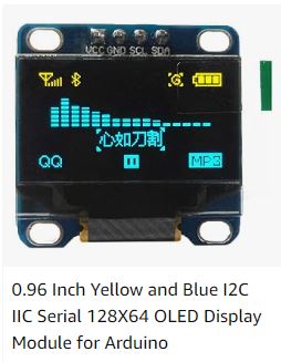
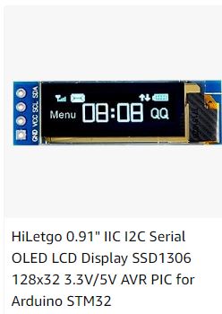
In the world of DIY electronics, Arduino projects continue to inspire creativity and innovation. In this blog post, we’ll explore an exciting Arduino project that combines the power of the NodeMCU 8266 microcontroller with a 0.96-inch OLED display to create a WiFi scanner. This project enables you to scan and display available WiFi networks in your vicinity. Whether you’re a beginner or an experienced maker, this tutorial will help you expand your skills and create a valuable tool for your Internet of Things (IoT) projects.
Youtube tutorial:
Components and Libraries:
Before we dive into the code, let’s take a moment to understand the components and libraries involved in this project:
Components:
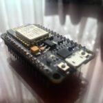
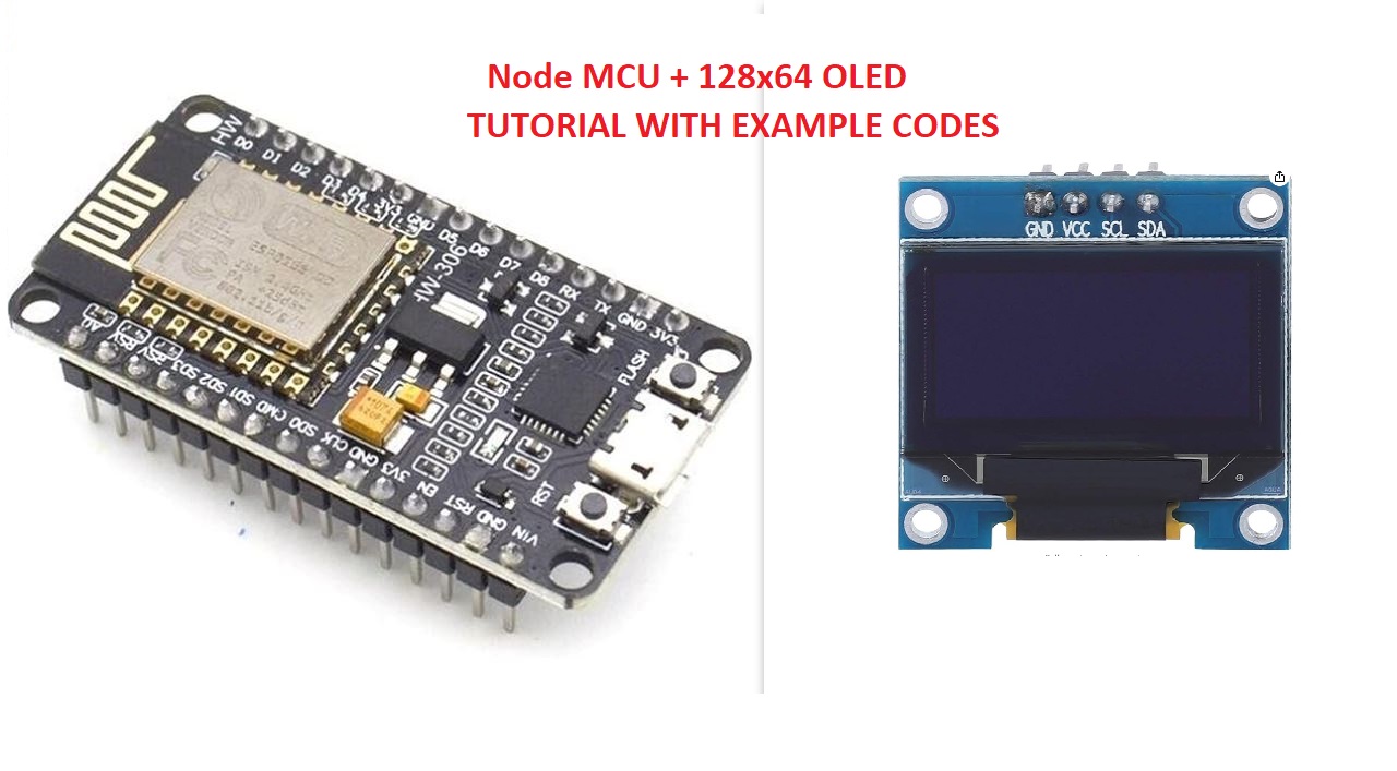
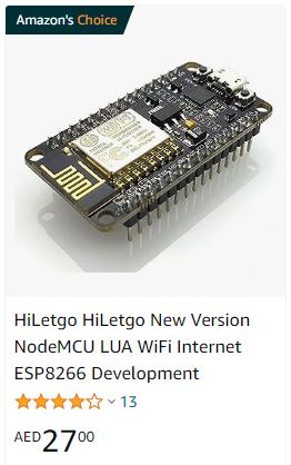
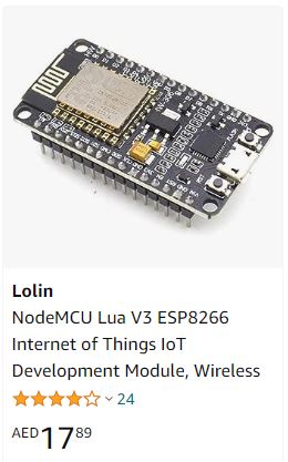
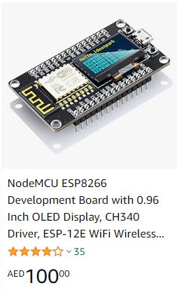
- NodeMCU 8266: A versatile microcontroller board based on the ESP8266 WiFi module.
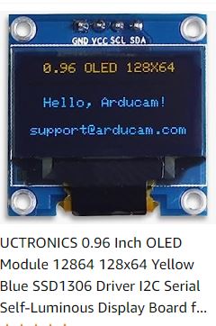
- 0.96 Inch OLED Display: A compact and low-power OLED screen for visualizing WiFi scan results.
- Jumper Wires: These are used for establishing electrical connections.
- USB Cable: Necessary for powering and programming the NodeMCU.
- Breadboard (optional): Useful for prototyping and making temporary connections.
Libraries:
- SPI: This library facilitates communication between your computer and the Arduino board.
- Wire: The Wire library enables I2C communication between the NodeMCU and the OLED display.
- Adafruit_GFX: This library provides various graphical functions for the OLED display.
- Adafruit_SSD1306: Used to control the OLED display and display text and graphics.
- ESP8266WiFi: An essential library for handling WiFi-related functions with the ESP8266 module.
Setting Up the OLED Display:
The OLED display is a crucial component in this project. It provides a visual platform for displaying WiFi scan results. Here’s how it’s set up:
- The display is initialized with the
display.begin()function, specifying the address (0x3C for 128×32 displays). - The display is cleared to create a blank canvas.
- You can customize the text size, color, and cursor position to control the appearance of your scan results.
Preparing for WiFi Scanning:
Before scanning for WiFi networks, it’s essential to set up the NodeMCU:
- The
WiFi.mode(WIFI_STA)function sets the WiFi mode to “station” mode, allowing it to connect to existing WiFi networks. WiFi.disconnect()is used to ensure the NodeMCU is not connected to any previously configured access points.
Scanning for WiFi Networks:
The core of this project is the WiFi scanning process, which is accomplished using the WiFi.scanNetworks() function. You can choose to scan asynchronously and include hidden networks in the results.
Displaying Scan Results:
Once the WiFi scanning is complete, the code is designed to display the results on the OLED screen. A noteworthy feature is the implementation of a scrolling text effect, which allows for the display of multiple network names, signal strengths (RSSI), encryption types, and other details.
Code:
#include <SPI.h> //Lib for SPI for PC to Arduino board
#include <Wire.h> //Lib for I2C communication between NodeMCU to OLED
#include <Adafruit_GFX.h> //lib for OLED
#include <Adafruit_SSD1306.h> // lib for OLED
#include <ESP8266WiFi.h> // lib for wifi

#define SCREEN_WIDTH 128 // OLED display width, in pixels
#define SCREEN_HEIGHT 64 // OLED display height, in pixels

// Declaration for an SSD1306 display connected to I2C (SDA, SCL pins)
// The pins for I2C are defined by the Wire-library.
// On an arduino UNO:       A4(SDA), A5(SCL)
// On an arduino MEGA 2560: 20(SDA), 21(SCL)
// On an arduino LEONARDO:   2(SDA),  3(SCL), ...
#define OLED_RESET     -1 // Reset pin # (or -1 if sharing Arduino reset pin)
#define SCREEN_ADDRESS 0x3C ///< See datasheet for Address; 0x3D for 128x64, 0x3C for 128x32
Adafruit_SSD1306 display(SCREEN_WIDTH, SCREEN_HEIGHT, &Wire, OLED_RESET);

//for scrolling effects
const int maxLines = 8; // Maximum lines to display
String textBuffer[maxLines];
int currentLine = 0;

void setup() {
  Serial.begin(115200);
  //------------------------------OLED setup ----------------------------------------
  if(!display.begin(SSD1306_SWITCHCAPVCC, 0x3C)) { // Address 0x3D for 128x64
    Serial.println(F("SSD1306 allocation failed"));
    for(;;);
  }
  delay(2000);
  display.clearDisplay(); //To clear the display
  display.setTextSize(1); // Size of the test
  display.setTextColor(WHITE); // Colour of text
  display.setCursor(0, 10); // Starting point of the cursor
  display.println("Booting..."); // Display static text
  display.display();
  delay(100);

  //------------------------wifi setup ---------------------
  display.clearDisplay(); //To clear the display
  display.setCursor(0, 10); // Starting point of the cursor
  display.println("WIFI loading"); // Display static text
  display.display();
  delay(100);
  display.clearDisplay(); //To clear the display

  WiFi.mode(WIFI_STA); // Set WiFi to station mode
  WiFi.disconnect(); // Disconnect from an AP if it was previously connected
  delay(100);
}

void loop() {

String ssid;
int32_t rssi;
uint8_t encryptionType;
uint8_t *bssid;
int32_t channel;
bool hidden;
int scanResult;

addLineToBuffer("---------------------");
addLineToBuffer("Starting WiFi scan...");
updateDisplay();
delay(1000);

scanResult = WiFi.scanNetworks(/*async=*/false, /*hidden=*/true); // Used for scanning wifi network in range.

if (scanResult == 0) {
  display.clearDisplay(); //To clear the display
  display.setCursor(0, 10); // Starting point of the cursor
  display.println("No networks found"); // Display static text
  display.display();
  } else if (scanResult > 0) {
    display.clearDisplay(); //To clear the display
    String msg = "networks found : %d";
    msg.replace("%d", String(scanResult));
    addLineToBuffer(msg);
    updateDisplay();
    delay(1000);

    for (int8_t i = 0; i < scanResult; i++) {
      WiFi.getNetworkInfo(i, ssid, encryptionType, rssi, bssid, channel, hidden);
      addLineToBuffer(ssid); // Display SSID
      updateDisplay();
      delay(1000);
    }

  }else {
    display.clearDisplay(); //To clear the display
    display.setCursor(0, 10); // Starting point of the cursor
    display.println("Wifi Scan Error"); // Display static text
    display.display();
  }
}

void updateDisplay() {  //Display buffer
  display.clearDisplay();
  int y = 0;
  for (int i = 0; i < maxLines; i++) {
    int index = (currentLine + i) % maxLines;
    display.setCursor(0, y);
    display.println(textBuffer[index]);
    y += 8; // Adjust this value based on the text size and font
  }
  display.display();
}

void addLineToBuffer(String line) { //adding new line to the displayu buffer
  textBuffer[currentLine] = line;
  currentLine = (currentLine + 1) % maxLines; // Wrap around if needed
}
Conclusion:
Building a WiFi scanner with NodeMCU 8266 and a 0.96-inch OLED display is not just a fun project; it’s a practical addition to your DIY electronics toolkit. You can use this tool to diagnose signal strengths in your area, locate and identify nearby WiFi networks, and gain insights into channel interference.
By following this tutorial, you’ll not only acquire valuable skills in electronics and programming but also have a practical WiFi scanning tool at your disposal. Whether you’re a hobbyist, student, or professional, this project will enhance your understanding of IoT and Arduino-based applications.
If you have questions or need assistance with the code, please don’t hesitate to ask in the comments section below. Be sure to subscribe for more exciting Arduino projects and tutorials, and happy tinkering!
